Skip to content

huawei ağ ekipmanlarında basit martini vpls uygulaması

aşağıdaki topoloji üzerinde huawei ağ ekipmanlarını kullanarak basit bir mpls martini vpls örneği yapalım.

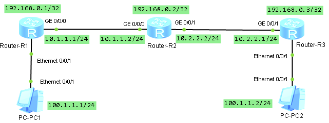
öncelikle loopback ve ip tanımlarını sırasıyla yapalım.

sysname R1

interface GigabitEthernet0/0/0
 ip address 10.1.1.1 255.255.255.0

interface LoopBack0
 ip address 192.168.0.1 255.255.255.255
sysname R2

interface GigabitEthernet0/0/0
 ip address 10.1.1.2 255.255.255.0

interface GigabitEthernet0/0/1
 ip address 10.2.2.2 255.255.255.0

interface LoopBack0
 ip address 192.168.0.2 255.255.255.255
sysname R3

interface GigabitEthernet0/0/1
 ip address 10.2.2.1 255.255.255.0

interface LoopBack0
 ip address 192.168.0.3 255.255.255.255

tüm arayüzler aktif olduktan sonra örnekte ospf yönlendirme protokolünü kullanacağımız için yönlendiriciler üzerinde ospf leri aktif etmek için gerekli yapılandırmasını yapalım.

sysname R1
ospf 1
 area 0.0.0.0
  network 192.168.0.1 0.0.0.0
  network 10.1.1.0 0.0.0.255
sysname R2
ospf 1
 area 0.0.0.0
  network 192.168.0.2 0.0.0.0
  network 10.1.1.0 0.0.0.255
  network 10.2.2.0 0.0.0.255
sysname R3
ospf 1
 area 0.0.0.0
  network 10.2.2.0 0.0.0.255
  network 192.168.0.3 0.0.0.0

ospf de aktif olduktan sonra mpls tanımlarına başlayabiliriz. tüm yönlendiriciler de global de mpls i aktif edelim.

mpls lsr-id 192.168.0.x
mpls
mpls l2vpn
mpls ldp

sonrasında ağımızda yönlendiriciler arasındaki arayüz bağlantıları altında mpls, mpls ldp aktif ediyoruz.

interface GigabitEthernet0/0/x
 mpls
 mpls ldp

en temel kontrolleri yaptık bir sorun görülmüyor. şimdi pc1 – pc2 arasındaki haberleşmenin sağlanması için gerekli yapılandırmaya sıra geldi. öncelikle r1 den r3 , r3 den r1 doğru ldp remote tanımlarını yapmalıyız.

sysname R1
mpls ldp remote-peer ldp_peer_to_r3
 remote-ip 192.168.0.3
sysname R3
mpls ldp remote-peer ldp_peer_to_r1
 remote-ip 192.168.0.1

şimdi yapabileceğimiz bazı kontrolleri yapalım.

<R1>display  mpls interface 
Interface             Status    TE Attr   LSP Count  CRLSP Count Effective MTU
GE0/0/0               Up        Dis       4          0           1500      
<R1>
<R1>display mpls ldp session 

 LDP Session(s) in Public Network
 Codes: LAM(Label Advertisement Mode), SsnAge Unit(DDDD:HH:MM)
 A '*' before a session means the session is being deleted.
 ------------------------------------------------------------------------------
 PeerID             Status      LAM  SsnRole  SsnAge      KASent/Rcv
 ------------------------------------------------------------------------------
 192.168.0.2:0          Operational DU   Passive  0000:01:45  423/423
 192.168.0.3:0          Operational DU   Passive  0000:01:53  455/455
 ------------------------------------------------------------------------------
 TOTAL: 2 session(s) Found.
[R1]display mpls route-state 
Codes: B(BGP), I(IGP), L(Public Label BGP), O(Original BGP), U(Unknow)
--------------------------------------------------------------------------------
Dest/Mask          Next-Hop        Out-Interface              State LSP VRF Type
--------------------------------------------------------------------------------

192.168.0.1/32         127.0.0.1       InLoop0                    READY 1   0      I
192.168.0.2/32         10.1.1.2        GE0/0/0                    READY 2   0      I
192.168.0.3/32         10.1.1.2        GE0/0/0                    READY 2   0      I
[R1]display mpls lsp 
-------------------------------------------------------------------------------
                 LSP Information: LDP LSP
-------------------------------------------------------------------------------
FEC                In/Out Label  In/Out IF                      Vrf Name       
192.168.0.2/32         NULL/3        -/GE0/0/0                                     
192.168.0.2/32         1028/3        -/GE0/0/0                                     
192.168.0.3/32         NULL/1025     -/GE0/0/0                                     
192.168.0.3/32         1029/1025     -/GE0/0/0                                     
192.168.0.1/32         3/NULL        -/-             

şimdi vsi ları oluşturalım. burada dikkat edilmesi gereken en önemli nokta vsi-id lerin aynı olması gerektiğidir.

sysname R1
vsi vsi_for_pc static
 pwsignal ldp
  vsi-id 100
  peer 192.168.0.3
sysname R3
vsi vsi_for_pc static
 pwsignal ldp
  vsi-id 100
  peer 192.168.0.1

son aşamaya gelmiş olduk. bilgisayarların bağlı arayüzler için tanımları da tapalım.

sysname R1
interface Ethernet0/0/1
 l2 binding vsi vsi_for_pc
sysname R3
interface Ethernet0/0/1
 l2 binding vsi vsi_for_pc

tüm yapılandırmaları tamamlamış olduk. şimdi bilgisayarlara ip leri girerek erişim kontrolleri yapalım. bilgisayarlarda ağ geçidi olarak karşı bilgisayarın iplerini girelim.

PC>ping 100.1.1.2

Ping 100.1.1.2: 32 data bytes, Press Ctrl_C to break
From 100.1.1.2: bytes=32 seq=1 ttl=128 time=94 ms
From 100.1.1.2: bytes=32 seq=2 ttl=128 time=156 ms
From 100.1.1.2: bytes=32 seq=3 ttl=128 time=62 ms
From 100.1.1.2: bytes=32 seq=4 ttl=128 time=94 ms
From 100.1.1.2: bytes=32 seq=5 ttl=128 time=110 ms

--- 100.1.1.2 ping statistics ---
  5 packet(s) transmitted
  5 packet(s) received
  0.00% packet loss
  round-trip min/avg/max = 62/103/156 ms

yönlendiricilere ait yapılandırmaların tam hali aşağıda yer almaktadır.

sysname R1

mpls lsr-id 192.168.0.1
mpls
mpls l2vpn
mpls ldp

vsi vsi_for_pc static
 pwsignal ldp
  vsi-id 100
  peer 192.168.0.3

mpls ldp remote-peer ldp_peer_to_r3
 remote-ip 192.168.0.3

interface Ethernet0/0/1
 l2 binding vsi vsi_for_pc

interface GigabitEthernet0/0/0
 ip address 10.1.1.1 255.255.255.0
 mpls
 mpls ldp

interface LoopBack0
 ip address 192.168.0.1 255.255.255.255

ospf 1
 area 0.0.0.0
  network 192.168.0.1 0.0.0.0
  network 10.1.1.0 0.0.0.255
sysname R2

mpls lsr-id 192.168.0.2
mpls
mpls ldp

interface GigabitEthernet0/0/0
 ip address 10.1.1.2 255.255.255.0
 mpls
 mpls ldp

interface GigabitEthernet0/0/1
 ip address 10.2.2.2 255.255.255.0
 mpls
 mpls ldp

interface LoopBack0
 ip address 192.168.0.2 255.255.255.255

ospf 1
 area 0.0.0.0
  network 192.168.0.2 0.0.0.0
  network 10.1.1.0 0.0.0.255
  network 10.2.2.0 0.0.0.255
sysname R3

mpls lsr-id 192.168.0.3
mpls
mpls l2vpn
mpls ldp

vsi vsi_for_pc static
 pwsignal ldp
  vsi-id 100
  peer 192.168.0.1

mpls ldp remote-peer ldp_peer_to_r1
 remote-ip 192.168.0.1

interface Ethernet0/0/1
 l2 binding vsi vsi_for_pc
 
interface GigabitEthernet0/0/1
 ip address 10.2.2.1 255.255.255.0
 mpls
 mpls ldp

interface LoopBack0
 ip address 192.168.0.3 255.255.255.255

ospf 1
 area 0.0.0.0
  network 10.2.2.0 0.0.0.255
  network 192.168.0.3 0.0.0.

huawei ağ ekipmanlarında basit ospf uygulaması

ospf detaylarına girmeden huawei ağ ekipmanlarında ospf nasıl kullanabiliriz ve kontrol edebiliriz aşağıdaki örnek topolojide incelemeye çalışalım.

yönlendiriciler üzerine öncelikle arayüz iplerini girelim

sysname R1

router id 192.168.0.1

interface Ethernet0/0/1
 ip address 192.168.100.1 255.255.255.0

interface GigabitEthernet0/0/0
 ip address 192.168.1.1 255.255.255.252

interface LoopBack0
 ip address 192.168.0.1 255.255.255.255
sysname R2

router id 192.168.0.2

interface Ethernet0/0/1
 ip address 192.168.101.1 255.255.255.0

interface GigabitEthernet0/0/0
 ip address 192.168.1.2 255.255.255.252

interface LoopBack0
 ip address 192.168.0.2 255.255.255.255

arayüzlerin durumunu kontrol edelim

<R1>display ip interface brief 
*down: administratively down
!down: FIB overload down
^down: standby
(l): loopback
(s): spoofing
(d): Dampening Suppressed
The number of interface that is UP in Physical is 4
The number of interface that is DOWN in Physical is 8
The number of interface that is UP in Protocol is 4
The number of interface that is DOWN in Protocol is 8

Interface                         IP Address/Mask      Physical   Protocol  
Ethernet0/0/0                     unassigned           down       down      
Ethernet0/0/1                     192.168.100.1/24     up         up        
GigabitEthernet0/0/0              192.168.1.1/30       up         up        
GigabitEthernet0/0/1              unassigned           down       down      
GigabitEthernet0/0/2              unassigned           down       down      
GigabitEthernet0/0/3              unassigned           down       down      
LoopBack0                         192.168.0.1/32       up         up(s)     
NULL0                             unassigned           up         up(s)     
Serial0/0/0                       unassigned           down       down      
Serial0/0/1                       unassigned           down       down      
Serial0/0/2                       unassigned           down       down      
Serial0/0/3                       unassigned           down       down 

tüm arayüzlerimiz aktif durumda. yönlendirme tablolarını da kontrol edelim

<R1>display ip routing-table 
Route Flags: R - relay, D - download to fib
------------------------------------------------------------------------------
Routing Tables: Public
         Destinations : 7        Routes : 7        

Destination/Mask    Proto   Pre  Cost      Flags NextHop         Interface

      127.0.0.0/8   Direct  0    0           D   127.0.0.1       InLoopBack0
      127.0.0.1/32  Direct  0    0           D   127.0.0.1       InLoopBack0
    192.168.0.1/32  Direct  0    0           D   127.0.0.1       LoopBack0
    192.168.1.0/30  Direct  0    0           D   192.168.1.1     GigabitEthernet0/0/0
    192.168.1.1/32  Direct  0    0           D   127.0.0.1       GigabitEthernet0/0/0
  192.168.100.0/24  Direct  0    0           D   192.168.100.1   Ethernet0/0/1
  192.168.100.1/32  Direct  0    0           D   127.0.0.1       Ethernet0/0/1

R1 üzerinde görüleceği üzere pc1 den pc2 ye ulaşmak istersek R1 üzerinden gerekli yönlendirme yapılamayacaktır. bu yönlendirme işlemini ospf ile yapmaya çalışalım..

R1 üzerine area 0 oluşturalım ve cihaz üzerindeki tüm networkleri ekleyelim

[R1]ospf 1 router-id 192.168.0.1
[R1-ospf-1]area 0
[R1-ospf-1-area-0.0.0.0]network 192.168.100.0 0.0.0.255
[R1-ospf-1-area-0.0.0.0]network 192.168.1.0 0.0.0.3
[R1-ospf-1-area-0.0.0.0]network 192.168.0.1 0.0.0.0

r1 üzerinde ospf için gerekli ayarları yaptıktan sonra gerekli kontrolleri sağlayalım.

[R1]display  ospf lsdb 

	 OSPF Process 1 with Router ID 192.168.0.1
		 Link State Database 

		         Area: 0.0.0.0
 Type      LinkState ID    AdvRouter          Age  Len   Sequence   Metric
 Router    192.168.0.1     192.168.0.1        440  60    80000005       1
<R1>display ospf nexthop 

	 OSPF Process 1 with Router ID 192.168.0.1
		 Routing Nexthop information 

  Next hops: 
  Address         Type       Refcount  IntfAddr        Intf Name 
 ----------------------------------------------------------------
  192.168.100.1   Local      1         192.168.100.1   Ethernet0/0/1 
  192.168.1.1     Local      1         192.168.1.1     GigabitEthernet0/0/0 
  192.168.0.1     Local      1         192.168.0.1     LoopBack0 
<R1>display ospf routing 

	 OSPF Process 1 with Router ID 192.168.0.1
		  Routing Tables 

 Routing for Network 
 Destination        Cost  Type       NextHop         AdvRouter       Area
 192.168.0.1/32     0     Stub       192.168.0.1     192.168.0.1     0.0.0.0
 192.168.1.0/30     1     Stub       192.168.1.1     192.168.0.1     0.0.0.0
 192.168.100.0/24   1     Stub       192.168.100.1   192.168.0.1     0.0.0.0

 Total Nets: 3  
 Intra Area: 3  Inter Area: 0  ASE: 0  NSSA: 0 
[R1]display ip routing-table 
Route Flags: R - relay, D - download to fib
------------------------------------------------------------------------------
Routing Tables: Public
         Destinations : 7        Routes : 7        

Destination/Mask    Proto   Pre  Cost      Flags NextHop         Interface

      127.0.0.0/8   Direct  0    0           D   127.0.0.1       InLoopBack0
      127.0.0.1/32  Direct  0    0           D   127.0.0.1       InLoopBack0
    192.168.0.1/32  Direct  0    0           D   127.0.0.1       LoopBack0
    192.168.1.0/30  Direct  0    0           D   192.168.1.1     GigabitEthernet0/0/0
    192.168.1.1/32  Direct  0    0           D   127.0.0.1       GigabitEthernet0/0/0
  192.168.100.0/24  Direct  0    0           D   192.168.100.1   Ethernet0/0/1
  192.168.100.1/32  Direct  0    0           D   127.0.0.1       Ethernet0/0/1

şimdi R2 üzefinde ospf konfigürasyonu yapmaya başlayalım. ilk önce area 0 oluşturalım ve R1 arayünün ip networke ekleyelim ve değişimleri gözlemleyelim

<R1>display ospf lsdb

	 OSPF Process 1 with Router ID 192.168.0.1
		 Link State Database 

		         Area: 0.0.0.0
 Type      LinkState ID    AdvRouter          Age  Len   Sequence   Metric
 Router    192.168.0.2     192.168.0.2         35  36    80000003       1
 Router    192.168.0.1     192.168.0.1         31  60    80000009       1
 Network   192.168.1.1     192.168.0.1         31  32    80000002       0
<R1>display ospf routing

	 OSPF Process 1 with Router ID 192.168.0.1
		  Routing Tables 

 Routing for Network 
 Destination        Cost  Type       NextHop         AdvRouter       Area
 192.168.0.1/32     0     Stub       192.168.0.1     192.168.0.1     0.0.0.0
 192.168.1.0/30     1     Transit    192.168.1.1     192.168.0.1     0.0.0.0
 192.168.100.0/24   1     Stub       192.168.100.1   192.168.0.1     0.0.0.0

 Total Nets: 3  
 Intra Area: 3  Inter Area: 0  ASE: 0  NSSA: 0 
<R1>display ospf nexthop 

	 OSPF Process 1 with Router ID 192.168.0.1
		 Routing Nexthop information 

  Next hops: 
  Address         Type       Refcount  IntfAddr        Intf Name 
 ----------------------------------------------------------------
  192.168.100.1   Local      1         192.168.100.1   Ethernet0/0/1 
  192.168.1.1     Local      1         192.168.1.1     GigabitEthernet0/0/0 
  192.168.0.1     Local      1         192.168.0.1     LoopBack0 
<R1>display ip routing-table 
Route Flags: R - relay, D - download to fib
------------------------------------------------------------------------------
Routing Tables: Public
         Destinations : 7        Routes : 7        

Destination/Mask    Proto   Pre  Cost      Flags NextHop         Interface

      127.0.0.0/8   Direct  0    0           D   127.0.0.1       InLoopBack0
      127.0.0.1/32  Direct  0    0           D   127.0.0.1       InLoopBack0
    192.168.0.1/32  Direct  0    0           D   127.0.0.1       LoopBack0
    192.168.1.0/30  Direct  0    0           D   192.168.1.1     GigabitEthernet0/0/0
    192.168.1.1/32  Direct  0    0           D   127.0.0.1       GigabitEthernet0/0/0
  192.168.100.0/24  Direct  0    0           D   192.168.100.1   Ethernet0/0/1
  192.168.100.1/32  Direct  0    0           D   127.0.0.1       Ethernet0/0/1

R2 için diğer networkleride ekleyelim. yönlendirme tabloları , lsdb vb deki değişimleri gözlemleyelim.

ospf 1 router-id 192.168.0.2
 area 0.0.0.0
  network 192.168.1.0 0.0.0.3
  network 192.168.0.2 0.0.0.0
  network 192.168.101.0 0.0.0.255

tüm networkleri r2 üzerinde tamamladıktan sonra yönlendirme tablosunu kontrol ederek pc1 den pc2 ye erişimi kontrol edelim.

<R1>display ospf routing 

	 OSPF Process 1 with Router ID 192.168.0.1
		  Routing Tables 

 Routing for Network 
 Destination        Cost  Type       NextHop         AdvRouter       Area
 192.168.0.1/32     0     Stub       192.168.0.1     192.168.0.1     0.0.0.0
 192.168.1.0/30     1     Transit    192.168.1.1     192.168.0.1     0.0.0.0
 192.168.100.0/24   1     Stub       192.168.100.1   192.168.0.1     0.0.0.0
 192.168.0.2/32     1     Stub       192.168.1.2     192.168.0.2     0.0.0.0
 192.168.101.0/24   2     Stub       192.168.1.2     192.168.0.2     0.0.0.0

 Total Nets: 5  
 Intra Area: 5  Inter Area: 0  ASE: 0  NSSA: 0
PC>ping 192.168.101.1

Ping 192.168.101.1: 32 data bytes, Press Ctrl_C to break
From 192.168.101.1: bytes=32 seq=1 ttl=254 time=62 ms
From 192.168.101.1: bytes=32 seq=2 ttl=254 time=94 ms
From 192.168.101.1: bytes=32 seq=3 ttl=254 time=78 ms
From 192.168.101.1: bytes=32 seq=4 ttl=254 time=78 ms
From 192.168.101.1: bytes=32 seq=5 ttl=254 time=47 ms

--- 192.168.101.1 ping statistics ---
  5 packet(s) transmitted
  5 packet(s) received
  0.00% packet loss
  round-trip min/avg/max = 47/71/94 ms

alcatel sr de yönlendirme protokollerinde default değerler

Protocols – Default preference

Directly connected		- 0
Static routes			- 5
OSPF internal			- 10
IS-IS level 1 internal		- 15
IS-IS level 2 internal		- 18
RIP				- 100
OSPF external			- 150
IS-IS level 1 external		- 160
IS-IS level 2 external		- 165
BGP				- 170
Back To Top